
Burst Light
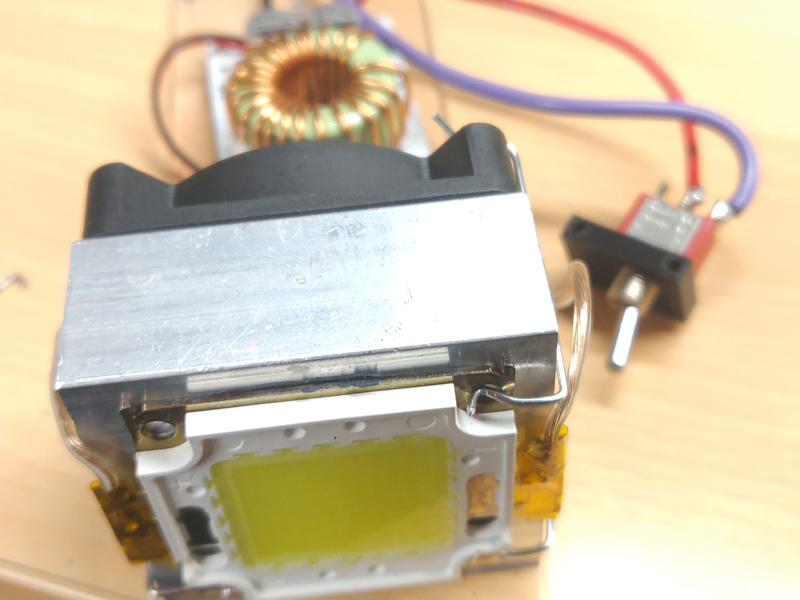 The screw holes in the LED don't have anything in them, so I used them as a convenient place to retain the clips.
 Next I attached the boost regulator to the mounting plate. I marked, drilled, and tapped holes in the plate first.
The alignment on this is not critical, so I used pan head screws instead of flat heads. The screws are smaller than the mounting holes, so there's a little bit of wiggle room. This comes in handy if the holes aren't drilled perfectly.
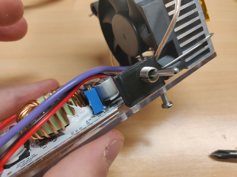 I 3D printed a small bracket to hold the switch. This is screwed in from the bottom.
This is where I soldered everything together during the original build.
 The battery bracket is prepped by inserting some battery straps and tapping all the holes.
The holes are too long to tap from one side with a standard tap. The top holes aren't being used right now though, so I just made sure to start tapping from the bottom.
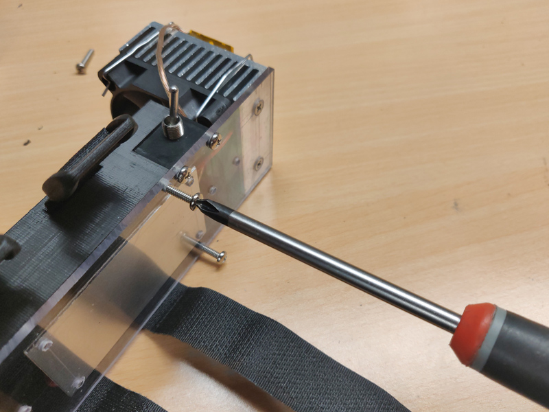 The battery bracket is attached with screws from the bottom, just like the switch bracket.